- modulo: Fade timing (lab)
- analog input: Potentiometer (lab)
- mapping: control LED with a Pot(lab)
- thresholds and calibration: Brightness sensor (lab)
- arrays and for loops: Multiple LEDs (lab)
- Button counter w/state change (lab)
Modulo:
Modulo is an mathematical operator that calculates the remainder when one integer is divided by another. It is very useful for keeping a number with in a set of numbers, or counting to a certain number over and over. Lets take a look at how it works:
0 % 4 = 0
1 % 4 = 1
2 % 4 = 2
3 % 4 = 3
4 % 4 = 0
5 % 4 = 1
6 % 4 = 2
7 % 4 = 3
8 % 4 = 0
The first number can keep growing but the result will only be a number between 0-3. If you modulo by 255, instead of 4, you have a great number to throw into the analogWrite() command to PWM a digital pin. Thats just what we are going to do. In fact lets make a simple "clock" and then a metronome.
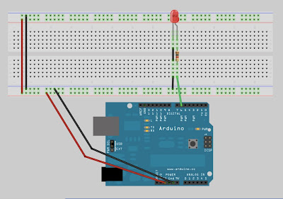
Using the function millis() returns the number of milliseconds since the Arduino has begun running a program. We can visualize the length of time the Arduino has been running a way that we recognize by chunking it into blocks of seconds, or fractions of seconds. Make the following circuit and then upload the corresponding code to make a simple clock.
/*
Simple Clock
Using % (modulo) and millis() to make a simple clock that
PWMs an LED to fractions of a second
Matt Richard
http://idblab.blogspot.com
*/
int pwmPin = 6;// digital pin to connect to LED
int pwmVal = 0;// variable that represents the PWM value for the LED to be placed in the analogWrite(pin, value) command.
int maxPWM = 256;// used with % to keep pwmVal between 0-255
int divisor = 2;// used to keep the increment of light and time relative
int pwmValIncrement = maxPWM / divisor;// if this # is a factor of 256 then the brightness steps will be even
int second = 1000;// number of milliseconds in one second
int time = second / divisor;// the increment in time that will trigger a change in the pwmVal
void setup() {
Serial.begin(115200);// begin a serial communication so we can see the millis count up.
}
void loop() {
// if the amount of time has passed then...
if(millis() % time == 0){
pwmVal = pwmVal + pwmValIncrement;// the value of the LED equals itself plus the LED light increment
pwmVal = pwmVal % maxPWM;// make sure the value of the LED is not greater than 255, if it is loop it back to 0
analogWrite(pwmPin, pwmVal);// PWM the led
Serial.println("time");// displays the change in light along side the change in millis
}
Serial.println(millis() % 1000);// displays the change in millis
}
Analog Input:
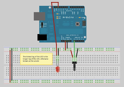
The Arduino has 6 pins that allow you to receive analog values from sensors attached to those pins. The Arduino determines the value by reading the voltage coming into those pins and comparing it to the Arduino standard voltage of 5volts dc. We are going to discover how this works by using a potentiometer. Create the circuit below and then upload the following code onto the Arduino.
/*
Analog Input with Potentiometer(pot)
using the arduinos analog input pins
Matt Richard
http://idblabs.blogspot.com
*/
int potPin = A0; // the pin which the middle pin of the potentiometer is attached
int potValue = 0; // the value that is sent from the potentimeter to the analog input pin
void setup() {
// create a serial connection so we can view the potentiometer readings in the serial monitor
Serial.begin(9600);
}
void loop() {
// read the value from the potentiometer
potValue = analogRead(potPin);
// display the value of the potentiometer in the serial monitor
Serial.println(potValue);
}
Now that we have used a potentiometer lets use the value to vary the delay between turning an LED on and off. Create the circuit below and then upload the following code onto the Arduino. The code is an example available with the Arduino ide found under 3.Analog/AnalogInput.
/*
Analog Input
Demonstrates analog input by reading an analog sensor on analog pin 0 and
turning on and off a light emitting diode(LED) connected to digital pin 13.
The amount of time the LED will be on and off depends on
the value obtained by analogRead().
The circuit:
* Potentiometer attached to analog input 0
* center pin of the potentiometer to the analog pin
* one side pin (either one) to ground
* the other side pin to +5V
* LED anode (long leg) attached to digital output 13
* LED cathode (short leg) attached to ground
* Note: because most Arduinos have a built-in LED attached
to pin 13 on the board, the LED is optional.
Created by David Cuartielles
Modified 4 Sep 2010
By Tom Igoe
This example code is in the public domain.
http://arduino.cc/en/Tutorial/AnalogInput
*/
int sensorPin = A0; // select the input pin for the potentiometer
int ledPin = 13; // select the pin for the LED
int sensorValue = 0; // variable to store the value coming from the sensor
void setup() {
// declare the ledPin as an OUTPUT:
pinMode(ledPin, OUTPUT);
}
void loop() {
// read the value from the sensor:
sensorValue = analogRead(sensorPin);
// turn the ledPin on
digitalWrite(ledPin, HIGH);
// stop the program for milliseconds:
delay(sensorValue);
// turn the ledPin off:
digitalWrite(ledPin, LOW);
// stop the program for for milliseconds:
delay(sensorValue);
}
Thresholds and Calibration:
The potentiometer generated a value from 0-1024 a even range to use as an input. Most sensors do not generate such a nice range of values under normal working conditions. To accurately map a sensor you need to now what the thresholds of the sensor. Each sensor will have a minimum and maximum threshold. Lets use a photocell to change the brightness of an LED. To do this first we will need to determine the minimum and maximum threshold of the photocell. Create the circuit below and then upload the following code onto the Arduino.
/*
Analog input from photocell to determine LED brightness
Matt Richard
http://idblab.blogspot.com
*/
int sensorPin = A0; // select the input pin for the potentiometer
int ledPin = 6; // select the pin for the LED
int sensorValue = 0; // variable to store the value coming from the sensor
int minThresh = 0;// replace this number with a lowest number from the serial monitor
int maxThresh = 1000;// replace this number with a highest number from the serial monitor
void setup() {
Serial.begin(9600);
}
void loop() {
// read the value from the sensor:
sensorValue = analogRead(sensorPin);
Serial.println(sensorValue);
analogWrite(ledPin, map(sensorValue, minThresh, maxThresh, 0, 255));
}
Once the program has been uploaded, open the serial monitor to view the incoming values from the photocell. Make note of the value of the photocell in ambient light, this is your maximum threshold. Now cover the photocell with your hand or an object to make it as dark as you can. This value is your minimum threshold. I like to add a small buffer of +-20 to insure that the photocell values do not go out of range under normal conditions, but make sure not to have a number less than 0. This is a simple way to calibrate your sensor. By replacing the values for minThresh and maxThresh with values from the serial monitor the effect of dimming the LED by placing your hand over the photocell has a greater effect on the brightness of the LED.
Arrays and For Loops:
Arrays are a way of declaring multiple of the same type of variable in a row in memory. Usually they are used with the idea that the values are multiples of the same type of object. What I mean is while the value of the photocell is an integer it doesn't make sense to include it in an array of integers that represent the digital pins used to power LEDs. Arrays are declared a little differently then other variables. Here are a few ways to declare an array:
int myInts[6];// this creates an array that has 6 places but does not define what the values are
int myPins[] = {2, 4, 8, 3, 6};// this creates an array of 5 places and defines the values
int mySensVals[6] = {2, 4, -8, 3, 2};// this creates an array of 6 places but only defines the first 5 values
This is how you access the values that are store in the arrays above:
myPins[0] + 1 = 3
The number inside of the square brackets [ ] indicates which value to access. Arrays are 0 based, meaning the first value is considered the 0 place not the 1st place.
Here is how you change the value of an element of an array:
myPins[1] = 9;// now the values for myPins look like this: {2, 9, 8, 3, 6}
The real power of arrays is unleashed when combined with for loops. The structure of a for loop is a little confusing at first, but once you understand how to use them they are essential. Basically a for loop is a way of repeating a command a determined number of times. You can use an array to count from any number by any number to any number. This makes it perfect for working with arrays because instead of manually putting 0-4 inside of the [ ] to access the values of myPins array, you can use a variable.
Here is a for loop that prints the values of myPins array to the serial monitor:
for(int i = 0; i <>
Serial.print(myPins[i]);
Serial.print(", ");
}
Serial.println();
This snippet of code will display the values with a comma and space between each value and then a line break after the last element has been printed. I recommend that you take a look at the for loop link above. The guys at Arduino have a wonderful description of how the mechanics work.
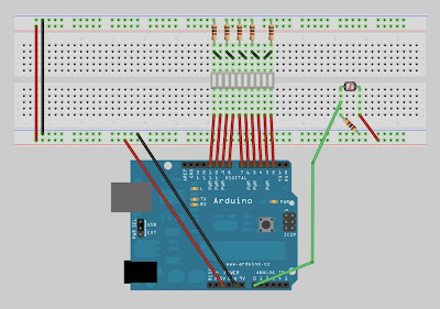
Lets put it into action so you can see how easy they are to use. Create the circuit below and then upload the following code onto the Arduino.
contains code to allow me to not mess styles
/*
Using an array of digital pins and a for loop to easily contol LEDs
with a mapped value from a photocell
As you can see, using arrays and for loops makes your code a lot smaller
and easy to change.
Matt Richard
http://idblab.blogspot.com
*/
int sensorPin = A0; // select the input pin for the potentiometer
int ledPins[] = {
2, 3, 4, 5, 6, 7, 8, 9, 10, 11};
/*
//how to write with out an array
int ledPin1 = 2;
int ledPin2 = 3;
int ledPin3 = 4;
int ledPin4 = 5;
int ledPin5 = 6;
int ledPin6 = 7;
int ledPin7 = 8;
int ledPin8 = 9;
int ledPin9 = 10;
int ledPin10 = 11;
*/
int sensorValue = 0; // variable to store the value coming from the sensor
int minThresh = 580;
int maxThresh = 870;
void setup() {
Serial.begin(9600);
for(int i = 0; i <>
pinMode(ledPins[i], OUTPUT);
}
/*
//how to write with out for loop
pinMode(ledPin1,OUTPUT);
pinMode(ledPin2,OUTPUT);
pinMode(ledPin3,OUTPUT);
pinMode(ledPin4,OUTPUT);
pinMode(ledPin5,OUTPUT);
pinMode(ledPin6,OUTPUT);
pinMode(ledPin7,OUTPUT);
pinMode(ledPin8,OUTPUT);
pinMode(ledPin9,OUTPUT);
pinMode(ledPin10,OUTPUT);
*/
}
void loop() {
// read the value from the sensor:
sensorValue = analogRead(sensorPin);
Serial.println(sensorValue);
controlLEDs();
}
void controlLEDs(){
int numLEDsOn = map(sensorValue, minThresh, maxThresh, 0, 10);
for(int i = 0; i <>
digitalWrite(ledPins[i], HIGH);
}
for(int j = numLEDsOn; j <>
digitalWrite(ledPins[j], LOW);
}
/*
// how to write without for loops and arrays
if(numLEDsOn == 0){
digitalWrite(ledPins1, LOW);
digitalWrite(ledPins2, LOW);
digitalWrite(ledPins3, LOW);
digitalWrite(ledPins4, LOW);
digitalWrite(ledPins5, LOW);
digitalWrite(ledPins6, LOW);
digitalWrite(ledPins7, LOW);
digitalWrite(ledPins8, LOW);
digitalWrite(ledPins9, LOW);
digitalWrite(ledPins10, LOW);
}
if(numLEDsOn == 1){
digitalWrite(ledPins1, HIGH);
digitalWrite(ledPins2, LOW);
digitalWrite(ledPins3, LOW);
digitalWrite(ledPins4, LOW);
digitalWrite(ledPins5, LOW);
digitalWrite(ledPins6, LOW);
digitalWrite(ledPins7, LOW);
digitalWrite(ledPins8, LOW);
digitalWrite(ledPins9, LOW);
digitalWrite(ledPins10, LOW);
}
if(numLEDsOn == 2){
digitalWrite(ledPins1, HIGH);
digitalWrite(ledPins2, HIGH);
digitalWrite(ledPins3, LOW);
digitalWrite(ledPins4, LOW);
digitalWrite(ledPins5, LOW);
digitalWrite(ledPins6, LOW);
digitalWrite(ledPins7, LOW);
digitalWrite(ledPins8, LOW);
digitalWrite(ledPins9, LOW);
digitalWrite(ledPins10, LOW);
}
if(numLEDsOn == 0){
digitalWrite(ledPins1, LOW);
digitalWrite(ledPins2, LOW);
digitalWrite(ledPins3, LOW);
digitalWrite(ledPins4, LOW);
digitalWrite(ledPins5, LOW);
digitalWrite(ledPins6, LOW);
digitalWrite(ledPins7, LOW);
digitalWrite(ledPins8, LOW);
digitalWrite(ledPins9, LOW);
digitalWrite(ledPins10, LOW);
}
if(numLEDsOn == 3){
digitalWrite(ledPins1, HIGH);
digitalWrite(ledPins2, HIGH);
digitalWrite(ledPins3, HIGH);
digitalWrite(ledPins4, LOW);
digitalWrite(ledPins5, LOW);
digitalWrite(ledPins6, LOW);
digitalWrite(ledPins7, LOW);
digitalWrite(ledPins8, LOW);
digitalWrite(ledPins9, LOW);
digitalWrite(ledPins10, LOW);
}
if(numLEDsOn == 4){
digitalWrite(ledPins1, HIGH);
digitalWrite(ledPins2, HIGH);
digitalWrite(ledPins3, HIGH);
digitalWrite(ledPins4, HIGH);
digitalWrite(ledPins5, LOW);
digitalWrite(ledPins6, LOW);
digitalWrite(ledPins7, LOW);
digitalWrite(ledPins8, LOW);
digitalWrite(ledPins9, LOW);
digitalWrite(ledPins10, LOW);
}
if(numLEDsOn == 5){
digitalWrite(ledPins1, HIGH);
digitalWrite(ledPins2, HIGH);
digitalWrite(ledPins3, HIGH);
digitalWrite(ledPins4, HIGH);
digitalWrite(ledPins5, HIGH);
digitalWrite(ledPins6, LOW);
digitalWrite(ledPins7, LOW);
digitalWrite(ledPins8, LOW);
digitalWrite(ledPins9, LOW);
digitalWrite(ledPins10, LOW);
}
if(numLEDsOn == 6){
digitalWrite(ledPins1, HIGH);
digitalWrite(ledPins2, HIGH);
digitalWrite(ledPins3, HIGH);
digitalWrite(ledPins4, HIGH);
digitalWrite(ledPins5, HIGH);
digitalWrite(ledPins6, HIGH);
digitalWrite(ledPins7, LOW);
digitalWrite(ledPins8, LOW);
digitalWrite(ledPins9, LOW);
digitalWrite(ledPins10, LOW);
}
if(numLEDsOn == 7){
digitalWrite(ledPins1, HIGH);
digitalWrite(ledPins2, HIGH);
digitalWrite(ledPins3, HIGH);
digitalWrite(ledPins4, HIGH);
digitalWrite(ledPins5, HIGH);
digitalWrite(ledPins6, HIGH);
digitalWrite(ledPins7, HIGH);
digitalWrite(ledPins8, LOW);
digitalWrite(ledPins9, LOW);
digitalWrite(ledPins10, LOW);
}
if(numLEDsOn == 8){
digitalWrite(ledPins1, HIGH);
digitalWrite(ledPins2, HIGH);
digitalWrite(ledPins3, HIGH);
digitalWrite(ledPins4, HIGH);
digitalWrite(ledPins5, HIGH);
digitalWrite(ledPins6, HIGH);
digitalWrite(ledPins7, HIGH);
digitalWrite(ledPins8, HIGH);
digitalWrite(ledPins9, LOW);
digitalWrite(ledPins10, LOW);
}
if(numLEDsOn == 9){
digitalWrite(ledPins1, HIGH);
digitalWrite(ledPins2, HIGH);
digitalWrite(ledPins3, HIGH);
digitalWrite(ledPins4, HIGH);
digitalWrite(ledPins5, HIGH);
digitalWrite(ledPins6, HIGH);
digitalWrite(ledPins7, HIGH);
digitalWrite(ledPins8, HIGH);
digitalWrite(ledPins9, HIGH);
digitalWrite(ledPins10, LOW);
}
if(numLEDsOn == 10){
digitalWrite(ledPins1, HIGH);
digitalWrite(ledPins2, HIGH);
digitalWrite(ledPins3, HIGH);
digitalWrite(ledPins4, HIGH);
digitalWrite(ledPins5, HIGH);
digitalWrite(ledPins6, HIGH);
digitalWrite(ledPins7, HIGH);
digitalWrite(ledPins8, HIGH);
digitalWrite(ledPins9, HIGH);
digitalWrite(ledPins10, HIGH);
}
*/
}
unless the resulting number would be less than 0.


